Air scrubber for H2S removal
RUH2S

CATEGORY ODOUR TREATMENT
TYPOLOGY ODOUR CONTROL UNITS
WHY TO USE IT
Normally, sulphides in waste originate from anaerobic biological processes through sulphate reduction. Solid or liquid waste containing H2S cause significant problems on the quality of life. Moreover, since the olfactory perception level of H2S is very low, it is difficult to verify the emissions at source, thus causing both asset and health damages. By using a system who catches the polluted air and a treatment with scrubber RUH2S type, both health problems and the real estate depreciation of the area where the source of odour is present can be avoided.
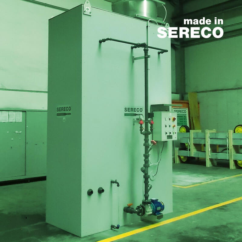
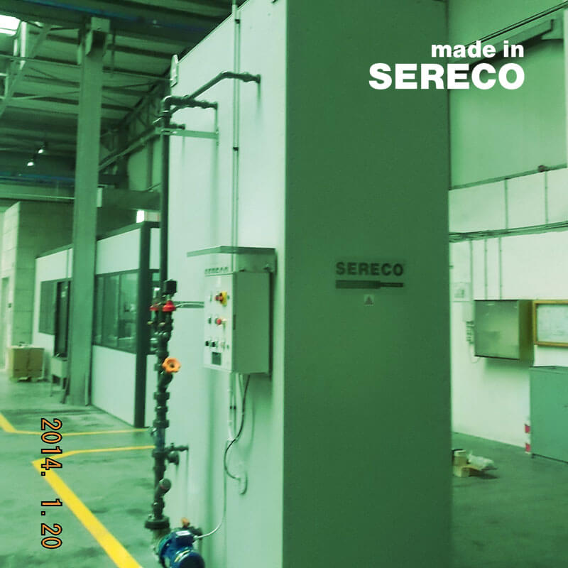
HOW IT IS MADE
The scrubber for odour treatment RUH2S type is mainly composed of: two towers in series for H2S chemical removal consisting of a lower air inlet connection; a set of filling material useful to distribute and bring into contact the incoming air which flows upwards and the washing liquid which flows downwards, optimizing the maximum contact; a suitable supporting structure for the filling material; a well-designed distributor of washing liquid, placed on the top of the column, which sprays the liquid on top of the filling material layer; washing liquid pumps; visual level indicators; level gauges useful to control and protect the respective washing liquid pumps against dry operation; centrifugal fan used to suck the polluted air and convey it to the scrubber; a caustic soda storage and dosing system; a sodium hypochlorite storage and dosing system; recirculation flow rate indicators; pack drop separator at scrubber outlet; outlet chimney.
HOW IT WORKS
The odour treatment system consist in removing or transforming the odorous compounds in order to reduce their concentration below the perception limit. This result is easily achieved by using the RUH2S system. A signal from the control chamber or from the local panel activates the chemical scrubber and the fan is immediately activated in order to suck the air to be treated and send it to the deodorising system. Also, the washing liquid pumps are immediately activated and start pumping the washing liquid (only caustic soda in the first process compartment, caustic soda and sodium hypochlorite in the second process compartment). The distributors spread the washing liquid in a shower of fine drops that fall on the alveolar material filling the towers. The incoming air to be treated enters in the washing tower from the tower connection with the fan outlet at the bottom of the first tower. Later, the air flows upwards in the first tower, crossing the support structure. When the air crosses the filling material, it is distributed in the column volume, coming into contact with the washing liquid, which flows downwards. Chemical removal takes place in this contact volume. The air moves toward the top of the column, while the washing liquid goes down, crossing the support structure and later it falls back into the washing liquid collectpion tank. The air to be treated is sent to the second process tower of the scrubber through a manifold that connects the outlet connection of the first tower to the inlet connection of the second tower. The second section operates in the same way as the first but with different washing liquid characteristics. The air coming out of the second tower passes through the droplet separator and, after being purified, exits from the top of the scrubber through the chimney.
STRENGTHS

CONSTRUCTION AND OPERATION EASINESS

REDUCED OCCUPIED SPACE

POSSIBILITY TO MANAGE THE PROCESS IN TOTAL COMPUTERIZED AUTONOMY

LOW OPERATING COSTS